Information Center
How to Design a Safe and Efficient Battery Charger Circuit
Published:2023-06-26 00:35:26 Author:Green WCND Views:54A battery charger circuit is an electronic circuit used to charge batteries. It converts AC power into a DC voltage suitable for charging batteries. There are different types of battery charger circuits that are used for different types of batteries such as lead acid, nickel-cadmium, and lithium-ion. The aim of this article is to outline the working principles and the design considerations for a battery charger circuit.
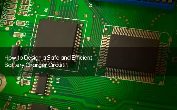
The working principle of a battery charger circuit is simple. It involves converting the AC input voltage to a DC voltage and then regulating it to ensure that the charging voltage and current are within the specified limits. The charging voltage depends on the type of battery being charged, and the charging current depends on the capacity of the battery.
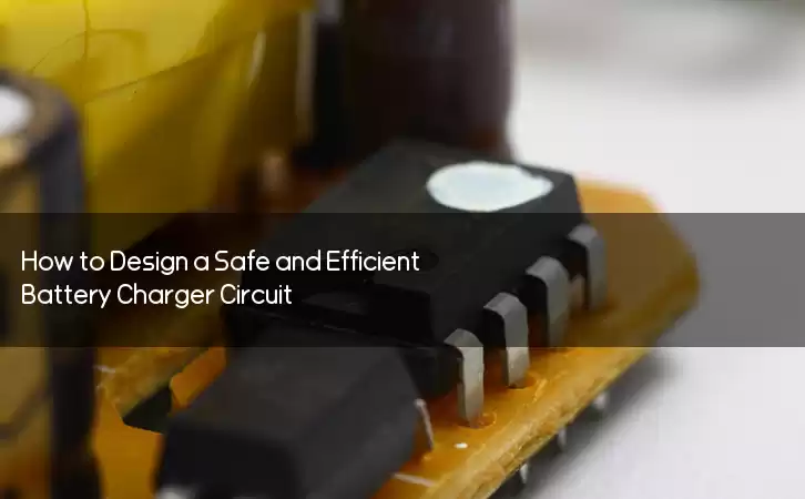
The first part of a battery charger circuit is a rectifier. The rectifier converts the AC voltage from the power source into a DC voltage. A diode bridge is the most common type of rectifier. It consists of four diodes arranged in a bridge configuration. The output of the diode bridge is a pulsating DC voltage.
The second part of the battery charger circuit is the filter. The filter removes the AC ripple from the pulsating DC voltage to produce a smooth DC voltage. The filter can be a capacitor or an inductor. Most battery charger circuits use both a capacitor and an inductor to produce a better filtering effect.
The third part of the battery charger circuit is the voltage regulator. The voltage regulator regulates the DC voltage to ensure that the charging voltage is within the specified limit. The voltage regulator can be a linear regulator or a switching regulator. A linear regulator is simple but inefficient, while a switching regulator is more complex but more efficient.
The fourth part of the battery charger circuit is the current regulator. The current regulator regulates the charging current to ensure that it is within the specified limit. The current regulator can be a linear regulator or a switching regulator. A switching regulator is more efficient than a linear regulator.
The design considerations for a battery charger circuit are as follows. The charging voltage and current should be within the specified limits for the battery being charged. The voltage regulator and current regulator should have good line and load regulation. The battery charger circuit should have overvoltage, overcurrent, and short-circuit protection. The battery charger circuit should also have a temperature sensor to ensure that the battery is not overcharged.
In conclusion, a battery charger circuit is an important electronic circuit used to charge batteries. The design of a battery charger circuit depends on the type of battery being charged and the charging voltage and current required. The working principle of a battery charger circuit involves converting AC power to DC power, filtering the DC power, and regulating the voltage and current. A well-designed battery charger circuit should have good regulation and protection features to ensure safe and efficient charging of batteries.
Power Adapter Design and Customization Guide for Portable Electric KettlesI. Common Design Types for Portable Electric Kettle Power AdaptersPortable electric ke···
I. Common Design Types of Power Adapters External Independent Type (Most Common) Design: A standalone adapter (e.g., "black brick") connected to the p···
Handheld Vacuum Cleaner Power Adapter Selection GuideIntroductionHandheld vacuum cleaners have become a mainstream tool for household cleaning due to their port···
Drill Power Adapter Selection Guide.drill-container { font-family: Arial, sans-serif; line-height: 1.6; max-width: 800px; margin: 0 auto; padding: 20px; } .dril···
