Unleashing the Power: Exploring the Components of a Battery Charger Circuit
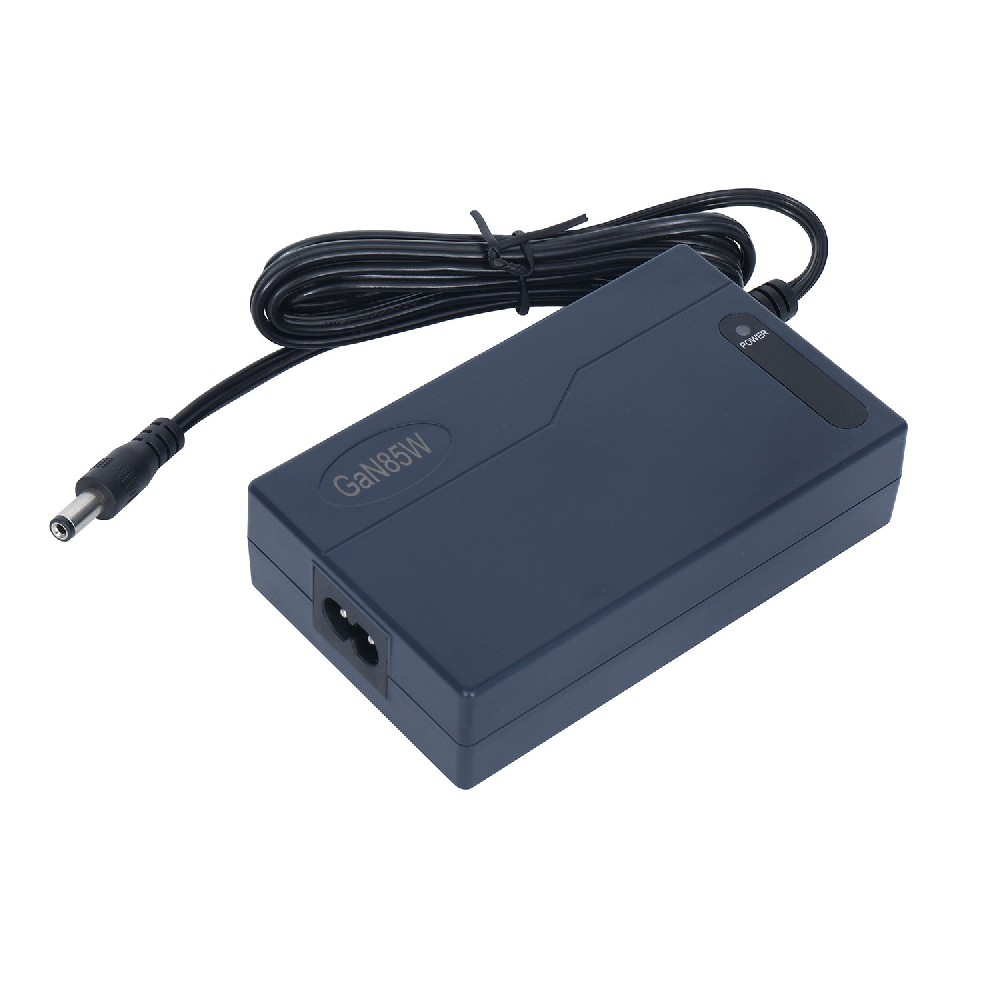
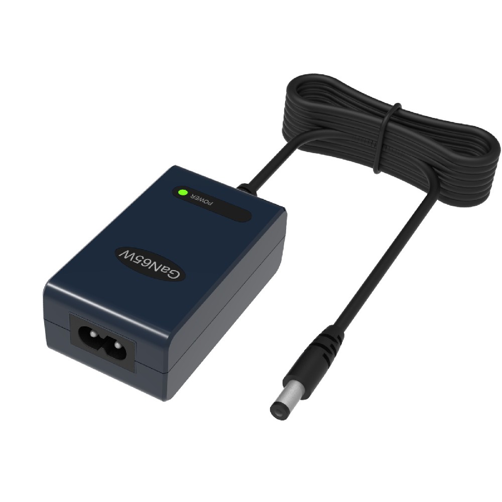
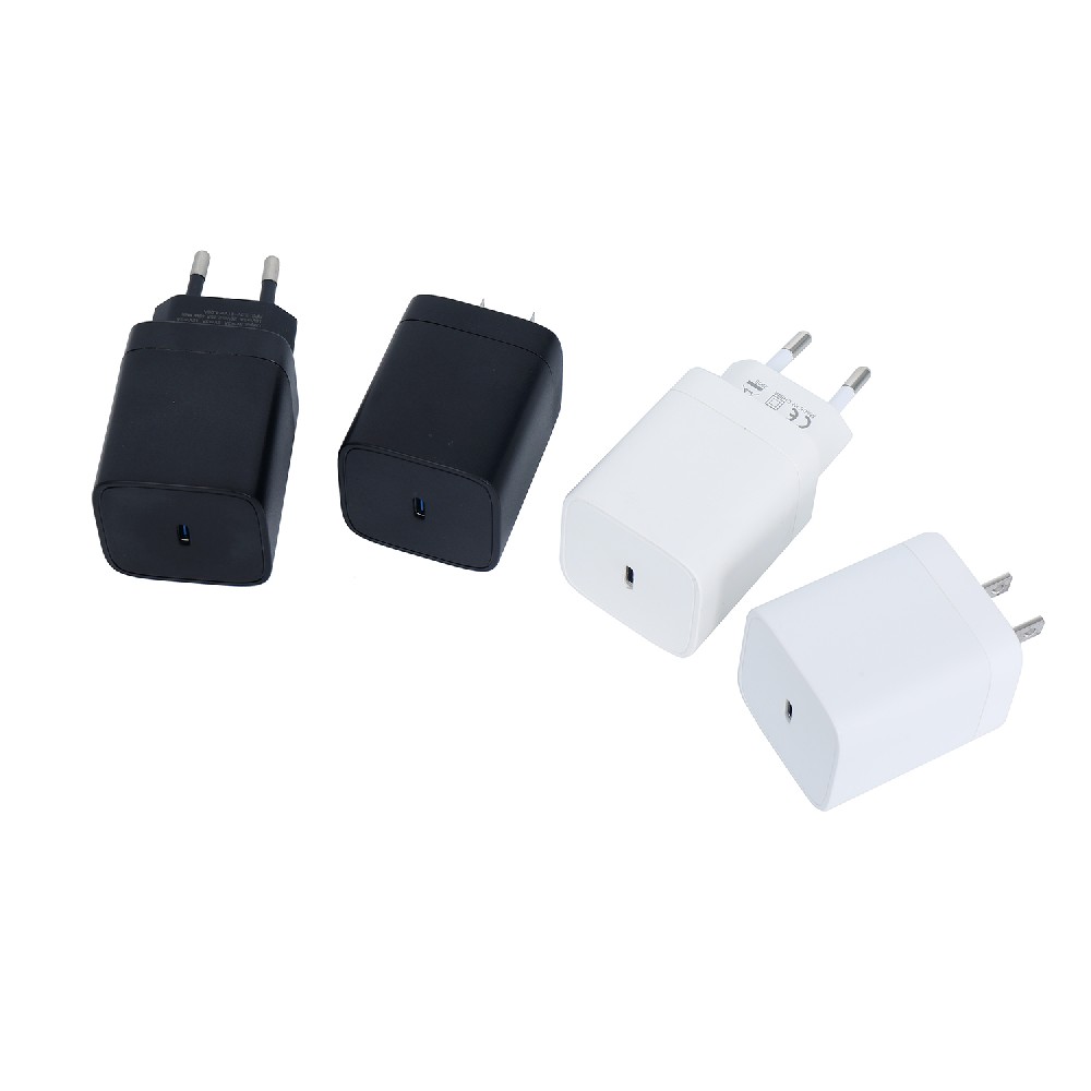
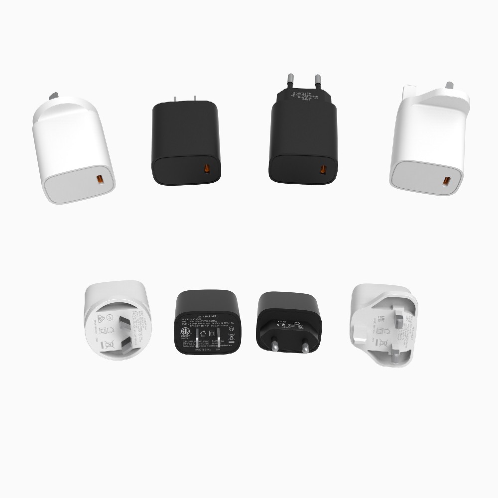
Published:2023-08-29 20:32:51 Author:Green WCND Views:37A battery charger circuit is an electronic device that is used to charge batteries. A battery charger circuit consists of various components such as resistors, capacitors, diodes, transistors, and inductors, among others. The primary function of a battery charger circuit is to convert AC power from the mains into DC power that can be used to charge a battery.

There are two main types of battery charger circuits: linear charger circuits and switch-mode charger circuits. A linear charger circuit is a simple circuit that uses a linear regulator to regulate the voltage and current supplied to the battery. A switch-mode charger circuit, on the other hand, is a more complicated circuit that uses a switching regulator to regulate the voltage and current supplied to the battery.

The basic components of a battery charger circuit include a transformer, a rectifier, and a regulator. The transformer is used to step down the AC voltage from the mains to a lower voltage level that can be used by the circuit. The rectifier is used to convert the AC voltage into DC voltage, while the regulator is used to regulate the voltage and current supplied to the battery.
There are different types of transformers that can be used in a battery charger circuit. The most common types are the step-down transformer and the auto-transformer. The step-down transformer is used to step down the AC voltage from the mains to a lower voltage level, while the auto-transformer is used to step down the voltage and increase the current supplied to the battery.
The rectifier used in a battery charger circuit can either be a half-wave rectifier or a full-wave rectifier. A half-wave rectifier is a simple circuit that uses only one diode to rectify the AC voltage, while a full-wave rectifier uses four diodes to rectify the AC voltage. The full-wave rectifier is more efficient and produces a smoother DC voltage output compared to the half-wave rectifier.
The regulator used in a battery charger circuit can either be a linear regulator or a switch-mode regulator. A linear regulator is a simple circuit that uses a transistor to regulate the voltage and current supplied to the battery. A switch-mode regulator, on the other hand, uses a switching transistor to regulate the voltage and current supplied to the battery. Switch-mode regulators are more efficient and produce less heat compared to linear regulators.
In conclusion, a battery charger circuit is an essential electronic device that is used to charge batteries. The choice of components used in a battery charger circuit depends on the type of battery being charged and the desired charging rate. The main components of a battery charger circuit include a transformer, a rectifier, and a regulator. The type of transformer, rectifier, and regulator used in a battery charger circuit depends on the desired charging rate and the efficiency of the circuit.
IntroductionGolf carts serve as vital transportation tools on golf courses, and their performance and reliability are crucial for enhancing player experience an···
The battery pack is the heart of a golf cart, silently powering every acceleration and climb on the green. However, battery degradation often goes unnoticed, mu···
The battery pack is the heart of a golf cart’s power system, yet maintaining it has long been a challenge for technicians. Traditional troubleshooting methods—···
For golf course managers, ensuring smooth and efficient operations is crucial for providing a memorable experience for golfers and maintaining the reputation of···


